Development of functional optical fiber demultiplexers (1994 – 1998)
1. Introduction
Array waveguide grating (AWG) devices with a demultiplexing function are
currently in widespread use for wavelength division multiplexing (WDM)
systems. Around 1990, however, optical fiber demultiplexers using a single
gradient index (GRIN) rod lens had just been developed.
In this work, we fabricated and tested functional optical fiber multiplexers
that have a multi-position switching function or a signal distribution
function (star coupler function).
2. Optical fiber demultiplexer with a multi-position switching function [1]
Figure 1 shows a schematic illustration of the functional device, which
consists of a star-shaped input/output optical fiber array, a gradient
index (GRIN) rod lens, and a rotatable grating prism (GRISM).
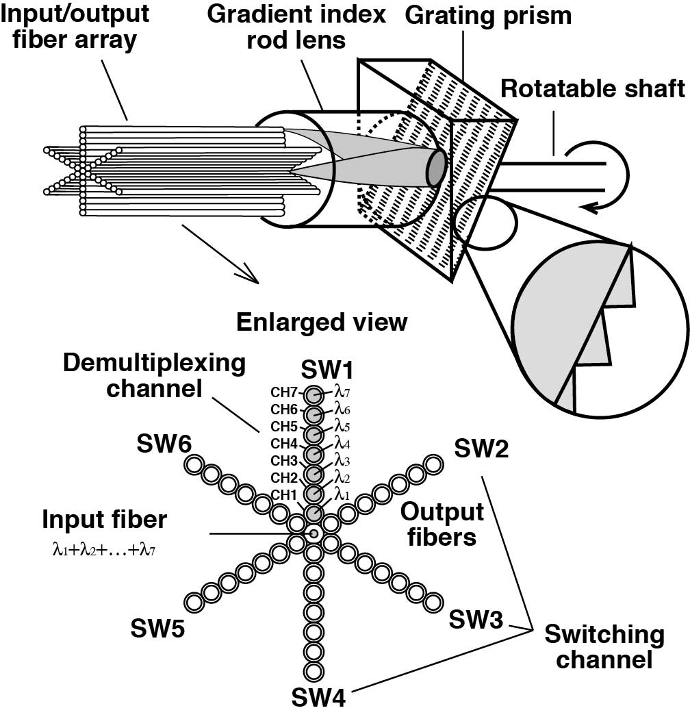
Fig. 1 Schematic illustration of the demultiplexer with a multi-position switching function.
The wavelength-multiplexed light from λ1 to λ7 enters the input optical fiber located at the center of the optical fiber
array. The input light is collimated through the GRIN rod lens, enters
the GRISM, and is then diffracted at different angles according to wavelength.
The diffracted light propagates in the reverse direction and is focused
on the different output optical fibers (CH1-CH7), which are aligned along
one radial direction. Therefore, one can obtain the demultiplexed beams
from the seven output fibers. One can select an individual set of output
fibers (SW1-SW6) by rotating the GRISM.
Figure 2 shows a photograph of the fabricated device and an image of the
transmitted light through the input/output optical fiber array. In our
experiments, we aligned the optical components using large high-precision
translation stages. Downscaling the device can be expected with the continuing
development of packaging technology.
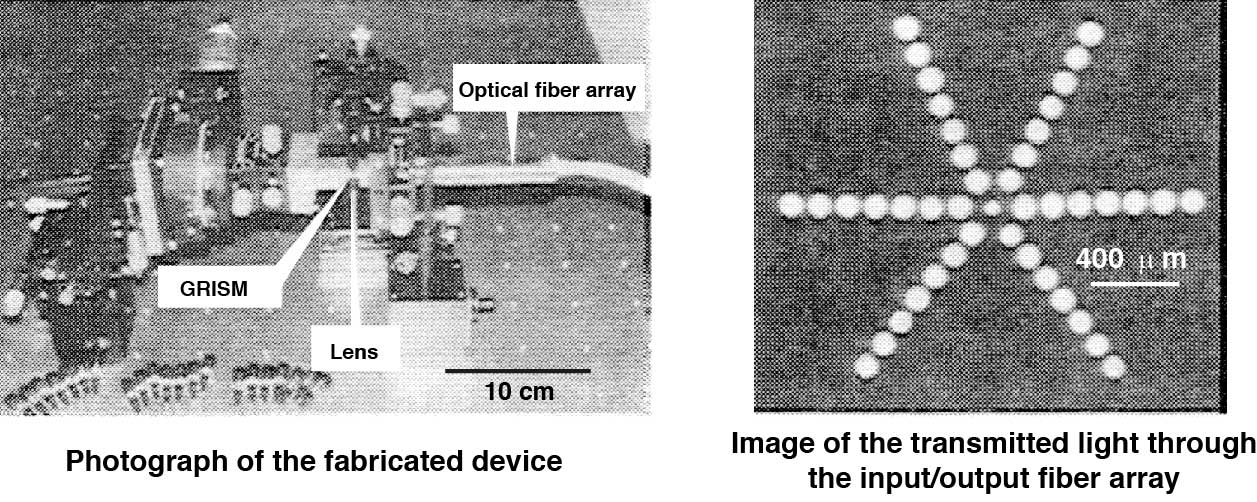
Fig. 2 Photograph of the fabricated device and an image of the transmitted light through the input/output fiber array.
The main characteristics of the fabricated device were as follows: 7 demultiplexing
channels, 6 switching channels, working wavelength region (0.64 – 0.88
μm), 3 dB bandwidth (18 – 22 nm), demultiplexing channel spacing (35 –
42 nm), minimum transmission loss for each demultiplexing channel (7.0
– 12.6 dB), channel crosstalk ( < -10 dB).
3. Optical fiber demultiplexer with a star coupler function[2]
Figure 3 shows a schematic illustration of the functional device. It consists
of a star-shaped input/output optical fiber array, a GRIN rod lens, and
a GRISM. Although this device is similar to that described in Section 2,
the grating prism consists of a hexagonal pyramid prism and six grating
facets.
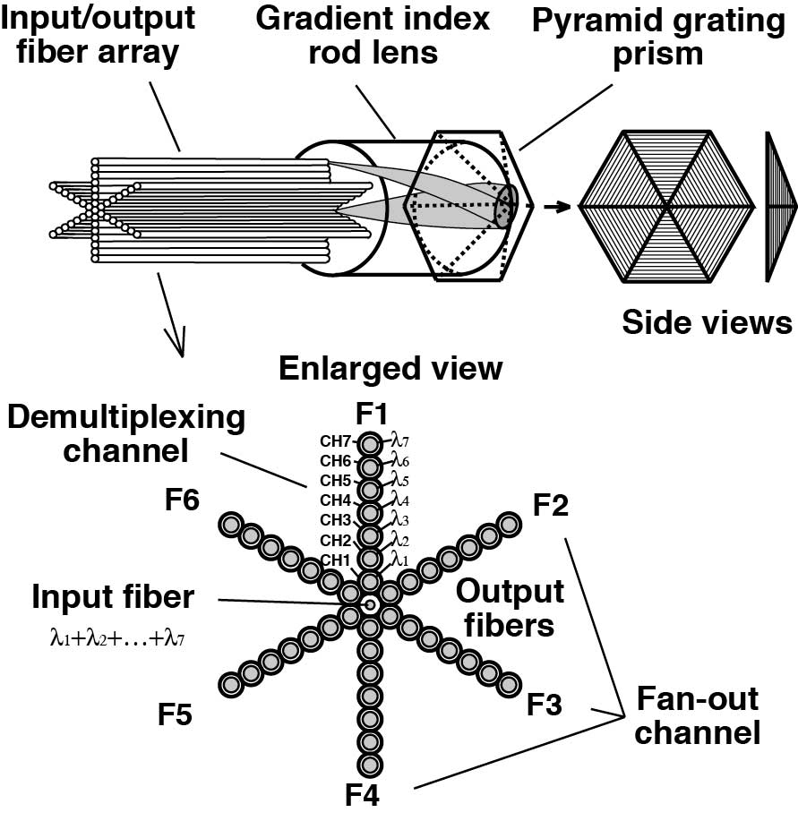
Fig. 3 Schematic illustration of the demultiplexer with a star-coupler function.
The wavelength multiplexed light from λ1 to λ7 enters the input optical fiber located at the center of the optical fiber
array. The input light is then collimated through the GRIN rod lens and
enters the GRISM, where it is divided into six beams by the six grating
facets. The six beams are then diffracted at different angles according
to wavelength. The diffracted beams propagate in the reverse direction
and are focused on the different output optical fibers (CH1-CH7), which
are aligned along the radial direction. Accordingly, one can simultaneously
obtain demultiplexed output beams from the six fan-out channels (F1-F6).
Figure 4 shows a photograph of our experimental setup for evaluating the
device characteristics, and an image of the transmitted light through the
input/output optical fiber array. Higher fabrication accuracy is necessary
for the input/output fiber array used in this device compared to that for
the optical fiber demultiplexer with the multi-position switching function
described in Sec. 2. The fabrication accuracy was improved in this fabrication.
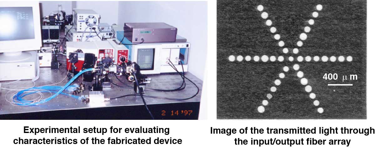
Fig. 4 Photograph of our experimental setup for evaluating the characteristics of the fabricated device, and an image of the light transmitted through the input/output fiber array.
The main characteristics of the fabricated device were as follows: 7 demultiplexing
channels, 6 fan-out channels, working wavelength region (0.62 – 0.88 μm),
3 dB bandwidth (13 – 24 nm), demultiplexing channel spacing (36 – 45 nm),
minimum transmission loss for each demultiplexing channel (7.4 – 17.2 dB),
channel crosstalk ( < -10 to -15 dB).
Acknowledgements
I would like to thank my collaborator, Prof. T. Sakamoto of Okayama Prefectural
University, for his proposal and design of the functional devices. I also
want to thank Sumitomo Electric Industries, Ltd. for providing me with
the optical fiber cables. This work was partially supported by the Electric
Technology Research Foundation of Chugoku.
References
[1] T. Fukushima and T. Sakamoto, A 7×6 optical fiber grating demultiplexer-multiposition
switch for 0.64-0.88 μm band, Journal of Lightwave Technology, vol. 14,
no. 5, pp. 867-872, 1996.
[2] T. Fukushima, T. Yokota, and T. Sakamoto, Fabrication of 7×6 multimode
optical fiber grating demultiplexer-star coupler using a single GRIN-rod
lens, Journal of Lightwave Technology, vol. 15, no. 10, pp. 1938-1946,
1997.